T-Mobile tests the durability of the mobile devices within a Heina Drop Tower as shown in video 0 below that drops devices above a concrete drop bed. This controlled free fall is designed to impact specific faces and edges. The mobile device is then retrieved, assessed for damage, and if acceptable reattached manually to the drop tower. The phone must be dropped in XX orientations, X times each for a total of 42 drops (if possible). The test must stop once the phone is cracked. Since this part of the durability test is manual, monotonous, and requires constant interaction from the operator, an automated process would free up the operator to perform other tasks.
Video 0: Heina DT2000S Drop Tower during normal operation; very slow.
Droppy was a retrofit robot that fit inside the exsisting Heina Drop Tower. It used a crack detection platform to scan for intial data on both sides of the phone, then the robotic arm placed the phone on the exsisiting drop tester's suction cup. When the arm moves out the way the drop occurs and phone is located, then picked up and placed in the crack dection platform. If no cracks are detected, the phone goes back to the exsisting suction cup on the drop tower for the next drop test. Process repeats until a failure occurs or all 42 drops are complete.
Video 1: Heina DT2000S Drop Tower installed with Droppy, first test cyle.
Droppy's core manipulation is conducting utilizing the commercial robotic arm, Dorna. Dorna is a five-degree-of-freedom robotic arm capable of highly repeatable and robust movements. Mounted to the end of Dorna is an effector composed of a single off-center vacuum cup. The vacuum system which provided suction to this cup is composed of a vacuum pump, solenoid to release the vacuum, and a pressure transducer to read if a vacuum was achieved. This armature is mounted to a 400mm power screw driven by a stepper motor. This linear actuator allowed Dorna to access all operation spaces in the horizontal plane. Together, Dorna and the power screw are mounted to two dual action pneumatic cylinders. These cylinders allow Dorna to reach both the drop bed and Heina's carriage. Droppy also consists of a crack detection platform with an Imaging Source monochromatic camera mounted to a lighting backdrop. Finally, an identical camera is mounted overhead to locate the device post-drop. These components are shown and labelled below in figure 3. Also included in this design, is a device restraining box which prevented the device from bouncing off the concrete drop bed.
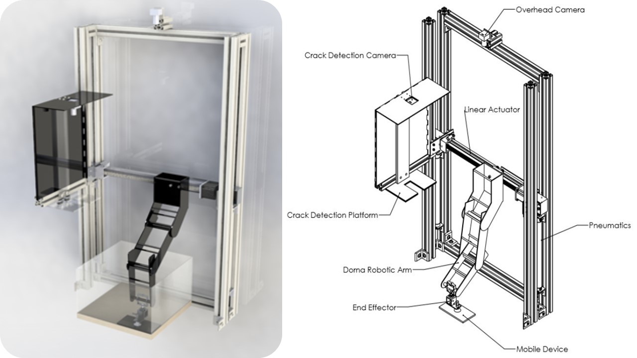
Figure 0: Nomenclature of robot and finalized CAD designed inside Heina Drop Tower.
Testing begins with, the operator placing the mobile device on the crack detection platform with the front of the phone facing up. The base images of the front of the new unblemished mobile device are then captured.The device is then flipped using Dorna. This flipping process begins the with the end effector slowly lowering over the center of the phone with the vacuum cup activated. Once suction is read by the vacuum transducer, the end effector stops lowering and the device is lifted from the platform.
Video 2: Droppy installed and working during first test run.
Droppy's core controller is the Intel NUC which handles communication between the individual systems. The systems which compose the nervous system of Droppy are a Raspberry Pi 3 B+ and the Dorna control box. The Raspberry Pi controls all mechanical components except for the Dorna robotic arm which is controlled via its own box.
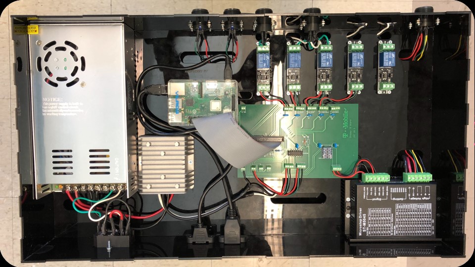
Figure 1: Droppy control box is paired with NUC (not shown).

Figure 2: Master electrical diagram.
Using EmguCV, a .Net wrapper to the OpenCV image processing library, the overhead camera captures an image of the drop box, and an edge detection algorithm is applied to the image. Based on a gray scale of 0 to 255, pixels in the image which are above the threshold value of 40 are accepted as edge pixels. Then, a contour algorithm is used to find all edges that form a rectangular shape. An example of this detection is shown above in figure 6. Once the rectangular shape is found, EmguCV class functions extract the rectangles center as x and y pixel coordinates. It also finds the angle of rotation of the device from the lowest point of the rectangle. Since the image is 72 pixels per inch, the pixel coordinates are then converted into inches. The coordinates in inches are then mapped to the robotic arm's coordinates to generate the devices center location and angle relative to the side walls of the drop box. The coordinate mappings are the image's x-direction to the robotic arm's y-direction, and the image's y-direction to the robotic arm's z-direction. The image's angle of rotation is then mapped to the robotic arm's angle of direction which is dependent on the quadrant of the image in which the device is found. The angle of rotation mappings are found through a set of continuous logic rules. These rules ensure that Dorna never attempts to move beyond its reach or damage the walls of the box. The robotic arm's y-direction, z-direction, and angle of rotation coordinates are then sent to Dorna.
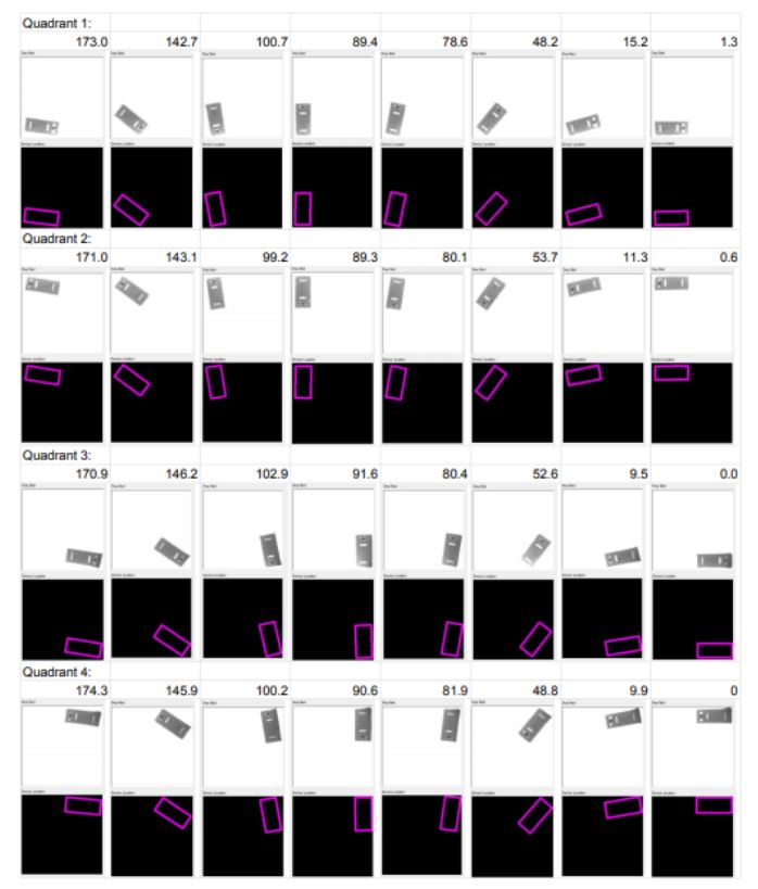
Figure 3: Locating the phone in different drop areas.
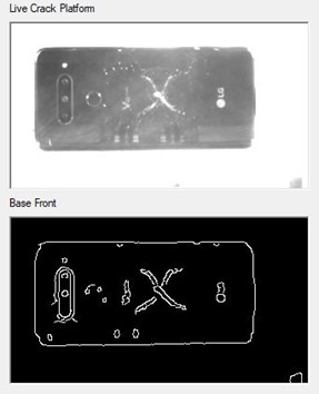
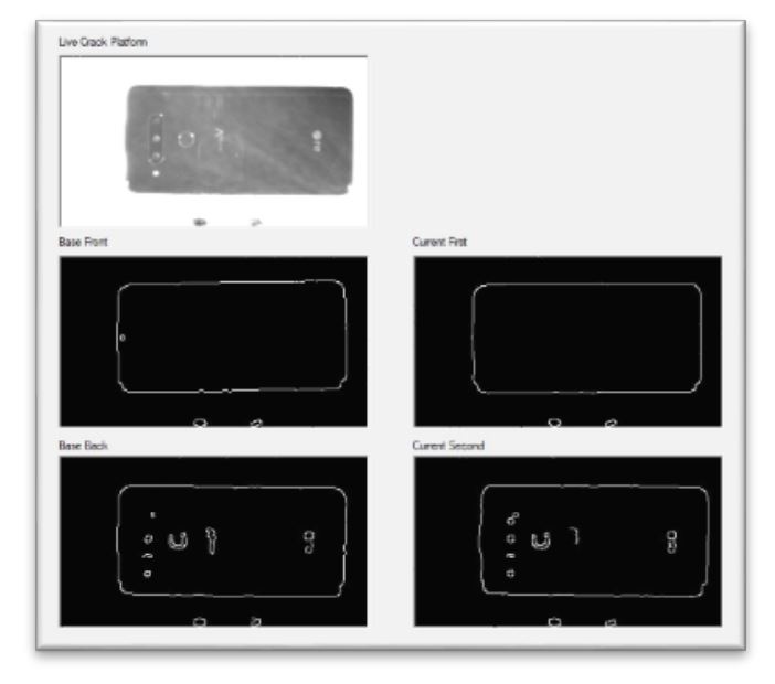
Figure 4: Crack detection example through monochromatic cameras.
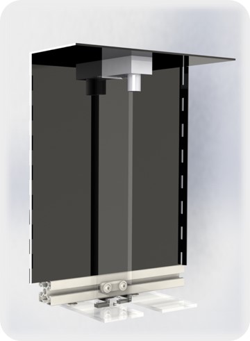
Figure 5: Crack detection platform.
Levon Markossian - 2021