HOME PAGE \
PDF SAMPLE DRAWINGS AVAILABLE
Mazdaspeed6 Transfer Case
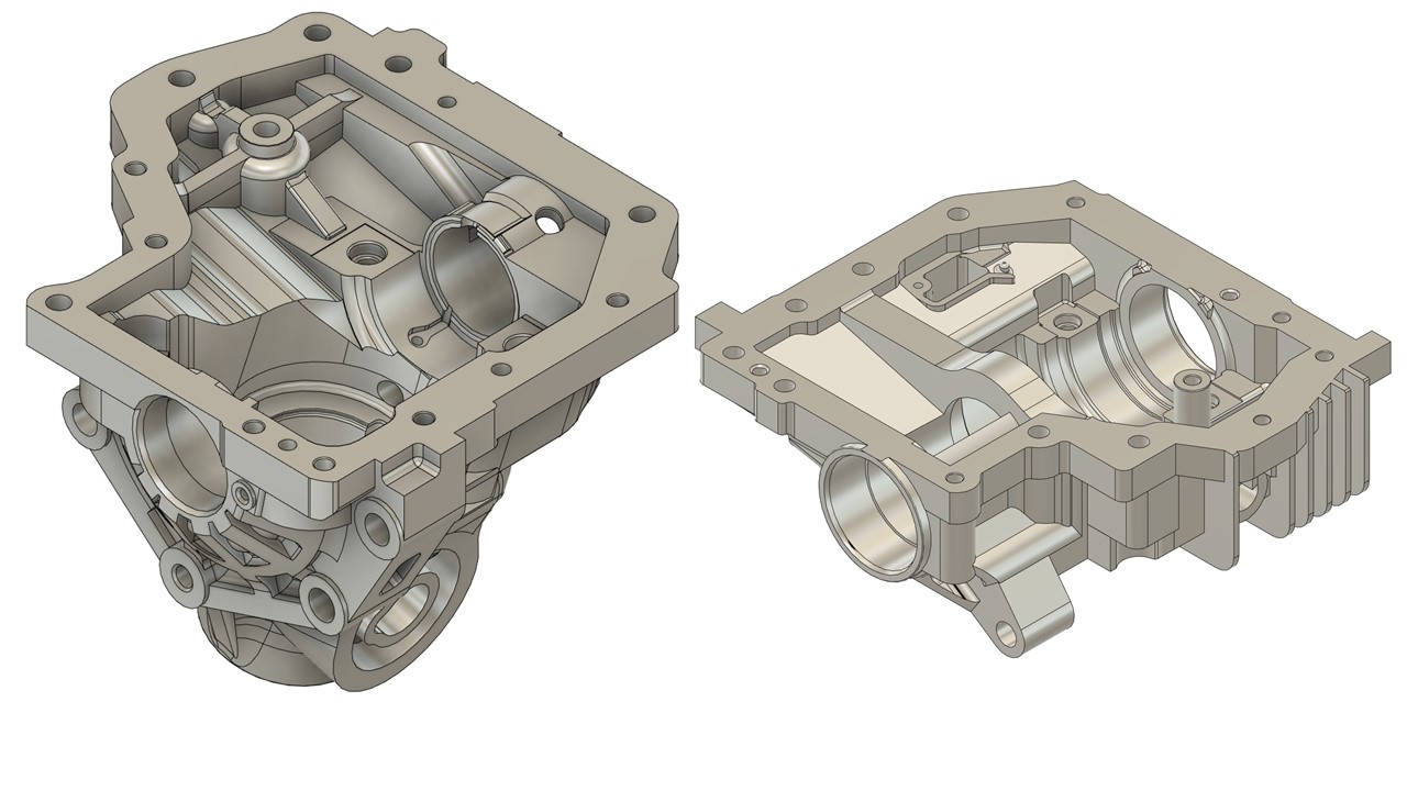
Figure 0: Finalized model of billet housing big half (left) small half (right).
Background and Failure
When launching at the drag strip and making an excess of 600-700 ft-lbs. of torque at the tire, the cast aluminum transfer case housing often explodes or cracks (figure 1). The transfer case bolts up to the transmission and sends power to the passenger tire and rear driveshaft. The two options for design solutions were a re-engineered billet housing based off factory measurements, or a retrofit kit that utilized an existing transfer case from another car (requires custom transmission bell housing to bolt up). Since the car's platform had a custom dog engagement transmission gear set already, enthusiasts opted for a re-engineered billet housing that bolted up like the factory housing.
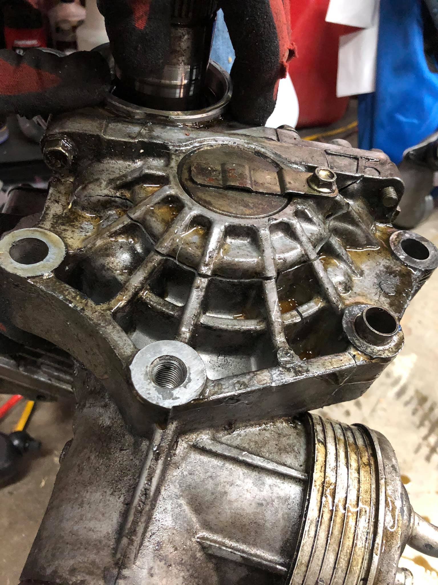
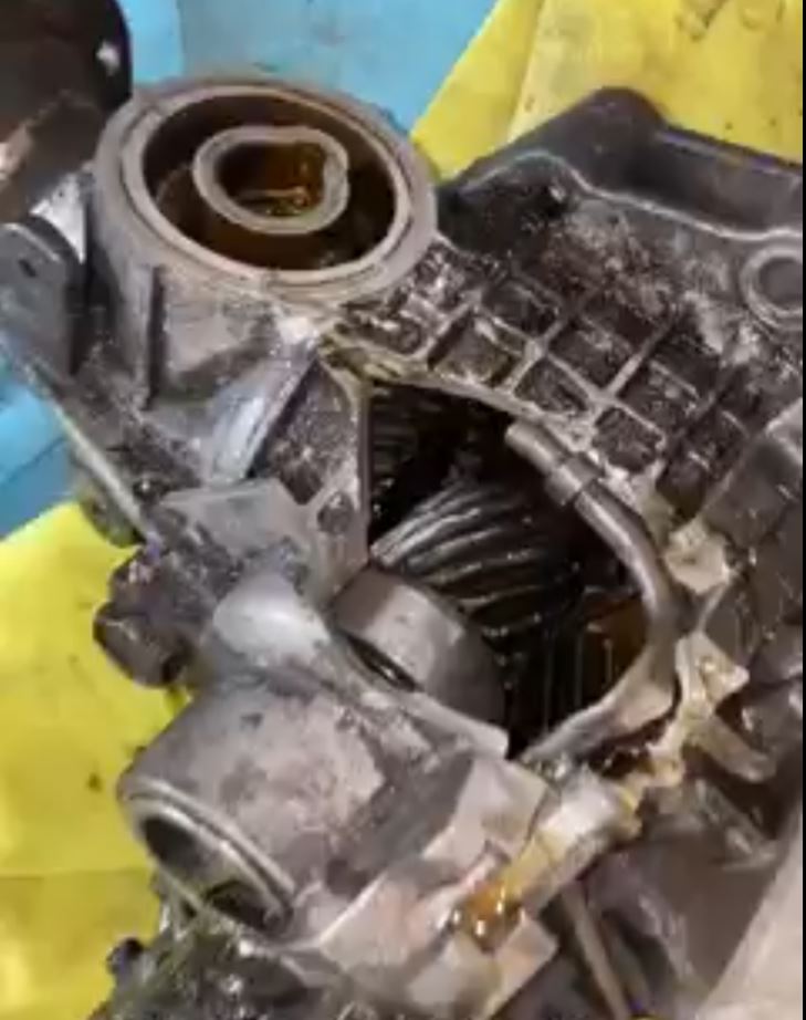
Figure 1: Examples of transfer case housings crack or break open (big half shown).
Design
- Since the drawing needed to be submitted in three months, no FEA or CFD analysis was done. The design process consisted of:
- Cloud point scan data was converted to 3D model to capture housing's interior cast geometry (figure 2).
- Critical measurements done on CMM, or bore gauge, height gauge.
- Billet design inspired from factory casting to match similar fluid flow and lubrication characteristics.
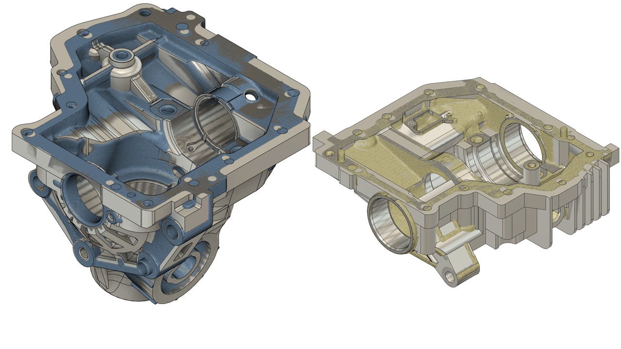
Figure 2: Cloud point scan data overlayed with brep model
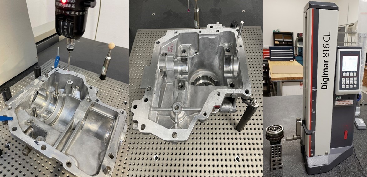
Figure 3: Critical distances measured on cmm (left and middle), and height gauge (right) to ensure proper bearing preload and gear engagement.

Figure 4: Critical diameters measured with dial bore gauge referenced off precision gauge blocks.
- 100-250% in added thickness all around. The material selection, 6063-T6, was much improved to handle more power than the cast housing from factory (figure 5).
- Housing bolts were upgraded to M10x1.25x40mm from M8x1.25x35mm.
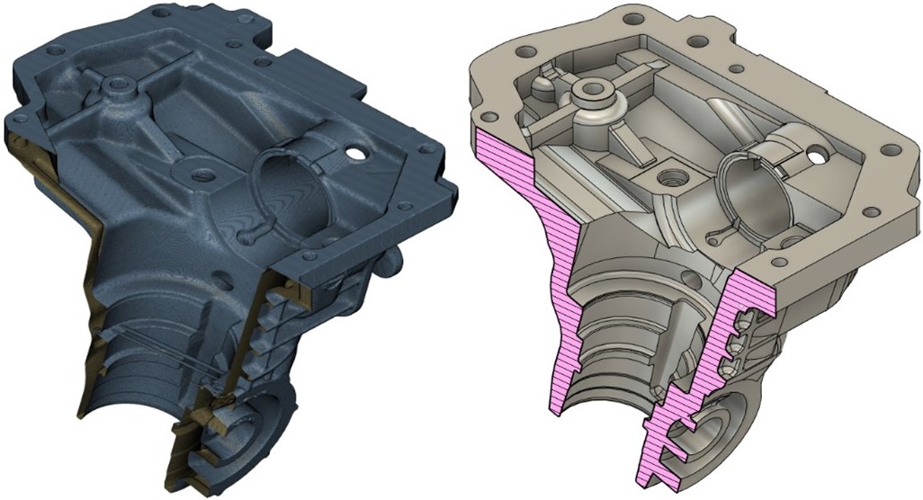

Figure 5: Displaying thickness change via section view, factory scan (left) new design (right).
- Fluid cooling was an unnecessary design constraint, but consideration was taken:
- The design is built around drag racing; cooling does not matter since the car is running only for a pass down the track. Cars are shut off after the race ends and usually don't have an alternator anyways.
- Factory oil cooler remains intact with similar volume capacity. Customers can run a block off plate too if they wish.
- Cooling fins removed from bigger half due to lack of airflow or less convection opportunity. The smaller half cooling fins were extended and optimized since it has a fresh air environment from underneath the car (figure 6).
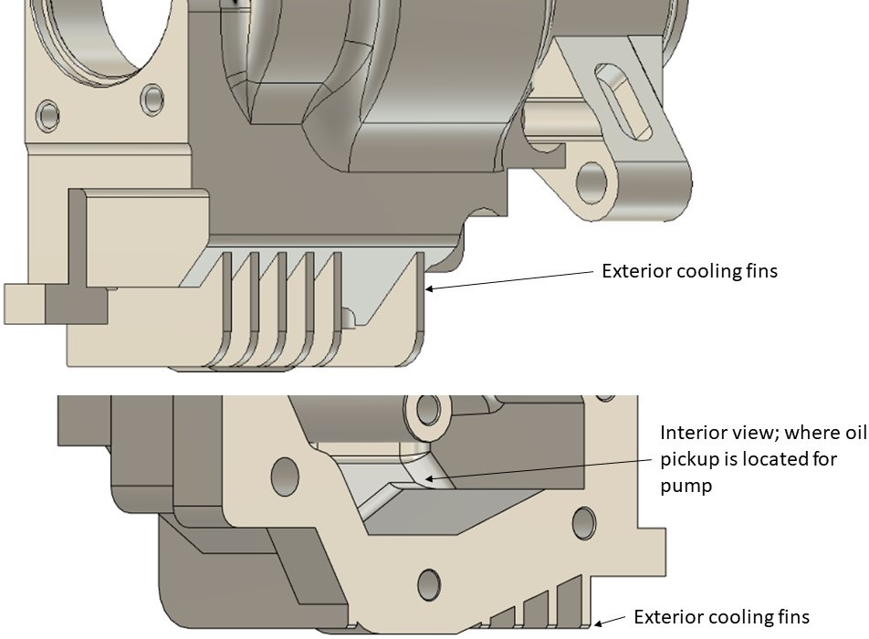
Figure 6: Cooling fins shown (exterior view top) with oil pickup location directly interior of fins for optimal cooling time (interior view bottom).
Manufacturing
- An aerospace machine shop ensures no dimensional errors and proper job. A typical machine shop -with most likely no metallurgy department- was less preferred.
- Many critical dimensions that cannot deviate from measured range, unless the customer wants to size different shims in the assembly to achieve the correct bearing preload and proper gear mesh. Besides bolt hole locations, all other dimensions are loose +/- .010 inch to +/- .050 inch.
- 6063-T6 was chosen over different aluminum grades because of manufacturing costs, decent thermal conductivity, excellent resistance to corrosion, and high strength (but ductile enough to handle drivetrain shock).
- Experiecned aerospace machine shop in Arizona offered to do the work at affordable cost. This only happened because of Greg's interest in the project and likes working with me. Part is currently being quoted and final tolerances are being discussed. Profit margin of around 50%-100% will be achieved depending on final quantity ordered.
- Pre-orders in the Mazda community will be placed soon.
Levon Markossian - 2021


