HOME PAGE \
PDF SAMPLE DRAWINGS AVAILABLE
Mazdaspeed6 Differential Mounts
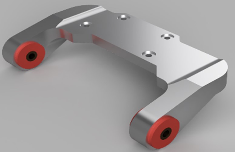
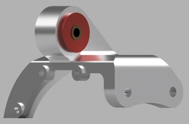
Figure 0: Finalized render of differential rear and front mount.
Background
It was becoming apparent that people were having trouble sourcing new differential mounts and the ones that already existed often failed. These mounts hold the differential underneath the car. The bushing sides are bolted to the subframe, and the main plate bolt holes line up with the differential's cast housing. When the driveshaft sends power to the rear of the car, the mounts feel the most stress cause by the force in the x and y direction (figure 1) and bending moment (figure 4).
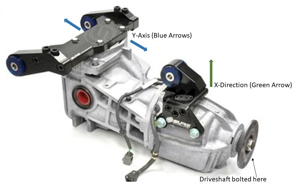
Figure 1: Differential shown with existing aftermarket mounts rear mount (left side), front mount (right side)
Photo from Sure Motorsports.
Rear Mount Failure Analysis, Improved Design Considerations, and Constraints
- The mounts that existed from previous companies had multiple iterations, but all failed. Most popular versions:
- One-piece aluminum cast design had a steep angled triangle leading up to each bushing side or leg. The steep angle concentrates the load and increase the stress on the main plate due to moment along axial direction. If the triangle was angled less aggressively the load would be distributed better along the main plate. During hard launches this would causing less deflection and no bending. Billet 6061 prototypes were made but still failed too. Geometry was copied from factory design, which was steel alloy cast not aluminum.
- Billet 6063-T6 three-piece version with 3/8 inch bolts driven in on each side. No bending occurred as it had thicker main plate, but these cracked due to the lack of material around the threads.
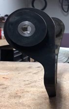

Figure 2: One piece aluminum cast or billet design bends due to lack of triangle optimization in leg
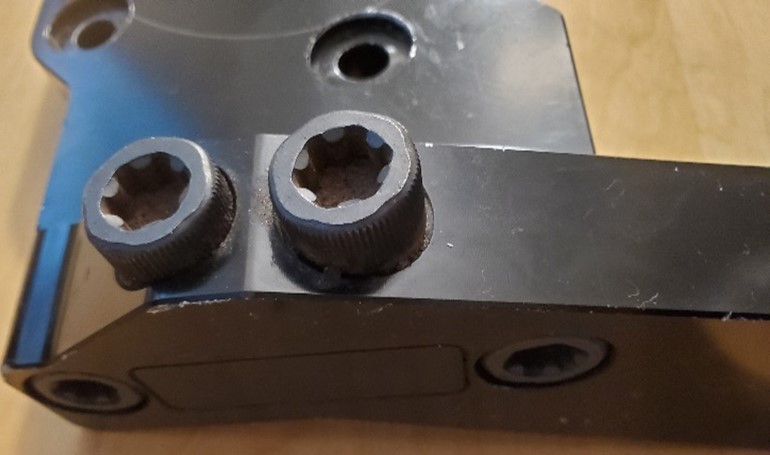
Figure 3: Bolted design also shown in figure 1
- New proposed design: Properly optimized one-piece 6063-T6 design because:
- Stronger than the competitor's previous one-piece design with leg's optimization.
- No cracking: Interference with mating parts occurs with a properly optimized 3/8 inch bolted design. More material is needed in the y-direction, but the sway bar interferes.
- Most affordable one-piece material for overseas manufacturing
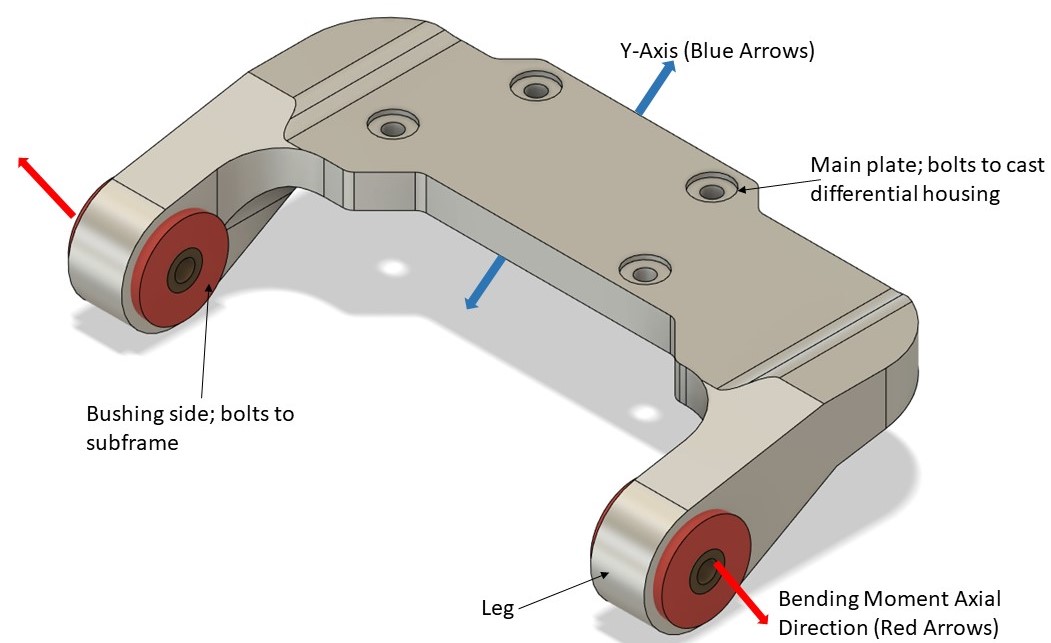
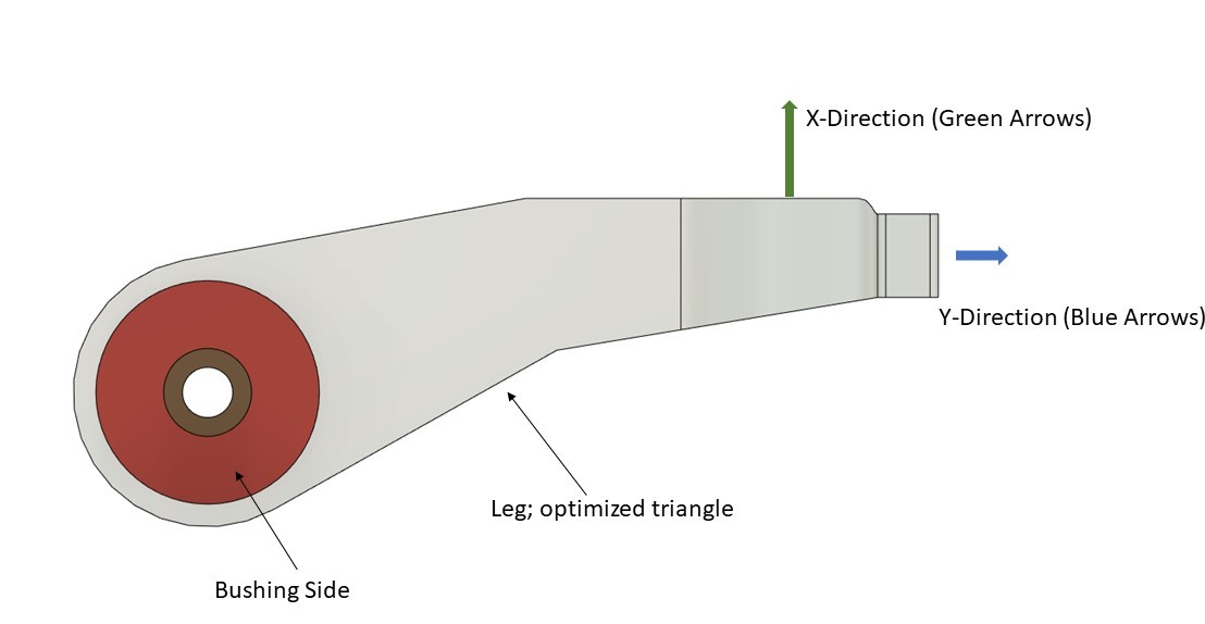
Figure 4: Rear mount breakdown of forces, bolting locations, and nomenclature.
- An FEA analysis was done against the previous design that bent. The goal was to ensure the new mount would not bend and had similar strength as the 3/8 inch bolt design that cracked:
- Various forces were applied on the bolts and simple statics calculation confirmed FEA results early on.
- Special attention was placed optimizing the leg's width verses main plate thickness. Since the bushings were off the shelf, only certain sizes were available thus controlling the required leg width.
- The previously mentioned triangle was optimized to be as least steep as possible, without interfering with mating parts such as the rear springs and rear sub frame.
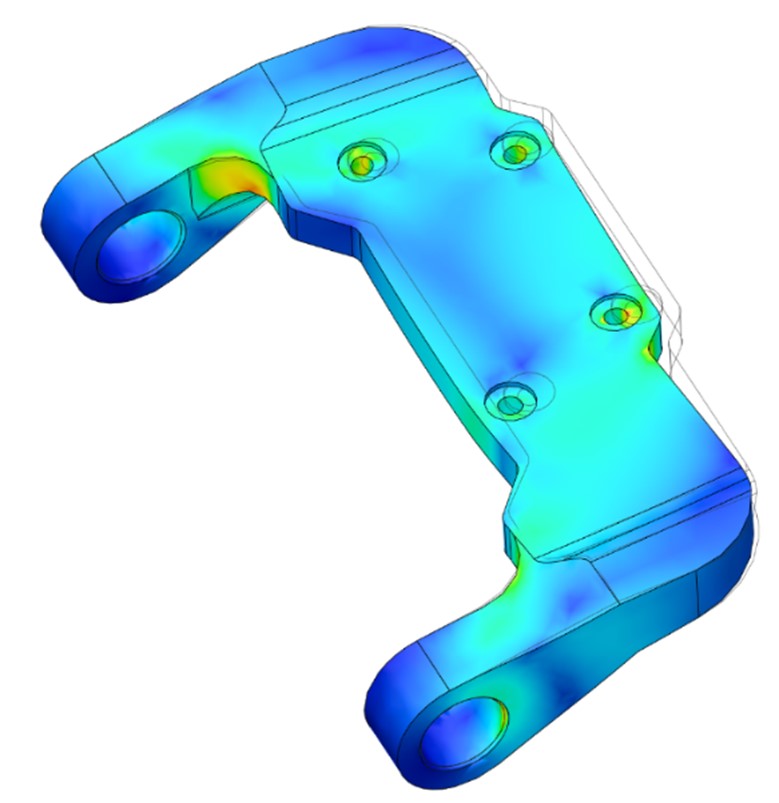
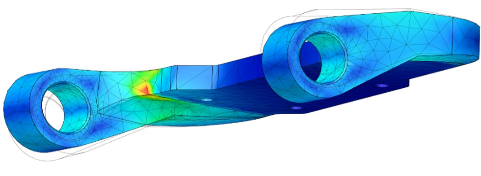
Figure 5: FEA on finalized design (Von Mises Shown).
Front Mount Failure Analysis, Improved Design Considerations, and Constraints
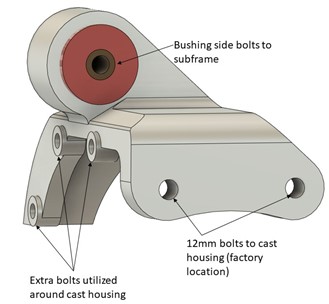
Figure 6: Front mount breakdown of forces, bolting locations, and nomenclature
- Factory cast differential housing cracks with every mount available currently due to bolts shearing casting in y-direction:
- In factory form, the mount just utilizes two 12mm housing bolts which often shear inside the housing. In extreme situations the housing's casting breaks around the 12mm bolts and can cause catastrophic failure once fluid bleeds out.
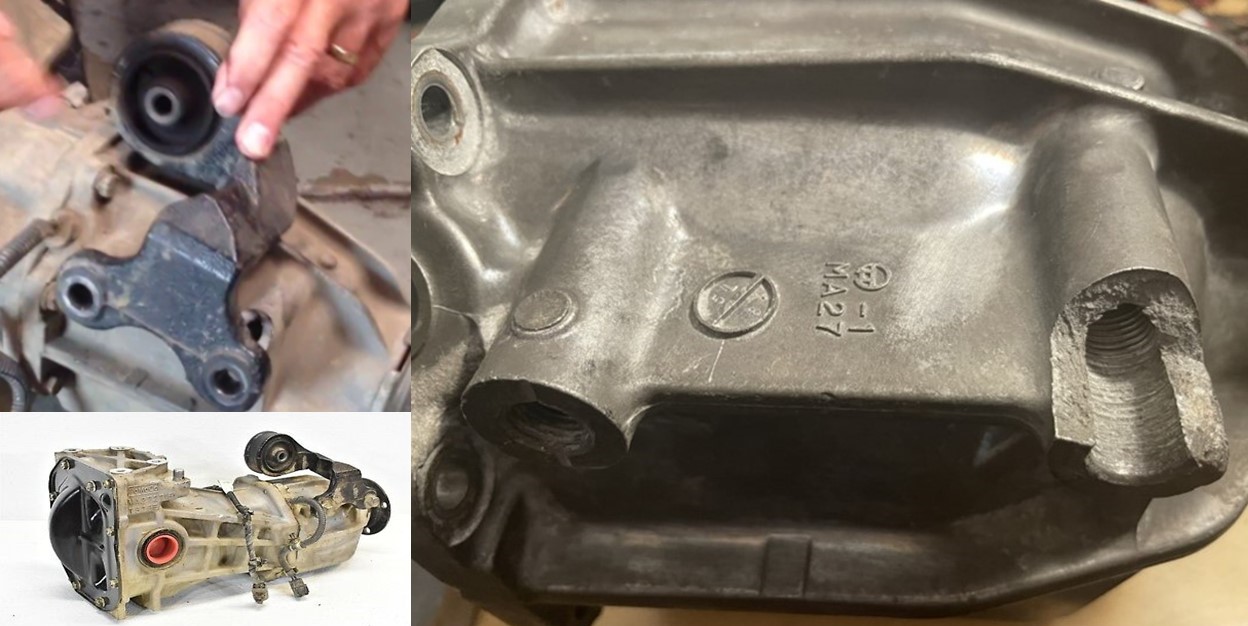
Figure 7: Factory housing utilizes two bolts that shear casting in y direction. Still occurs with aftermarket options on market.
- Previous aftermarket versions added extra bolts to distribute the load across the housing more but added problems elsewhere:
- Bent 1/4 inch plate with the no standoffs and the plate was not perpendicular to the 12mm case bolts face, a stress increaser is created all around housing (figure 8).
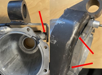
Figure 8: Lack of perpendicularity. Red arrow showing gap causing preload on bolts (left), red arrows display lack of flatness with no standoffs for extra bolts (right).
- New design had proper perpendicularity between the 12mm housing bolts and the new added bolting locations with proper 1/8 inch thick standoffs.
- Since the cast housing cracks already despite all the designs available (figure 7), no FEA analysis was done on the front mount.
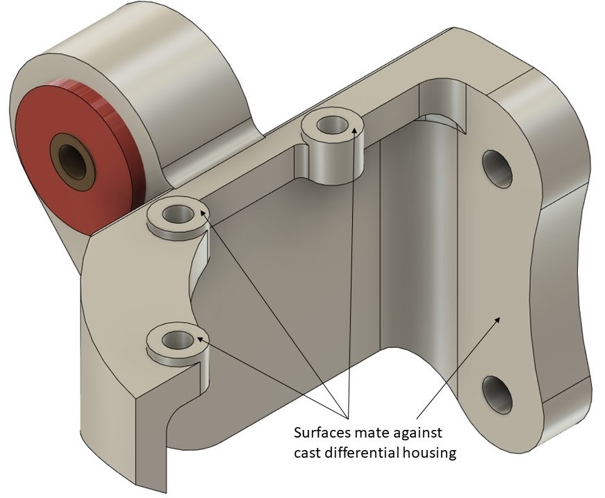
Figure 9: Perpedncualrity held .01 or better on these surfaces to prevent stress increasers and-or preload on bolts when torqued to cast housing.
Rear and Front Mount Manufacturing
- Part is in manufacturing process in China and quotes looked acceptable to move forward.
- Considering the size and cost of machining a one-piece design, the mounts can be sold competitively ($350-$400) while still yielding a 130-170% profit.
- Off the shelf bushings may need to change as there are issues sourcing them currently from Prothane.
- Custom bushings were deemed too expensive per this design.
- Many iterations of 3D printed parts to ensure proper fit and no interference with surrounding components.
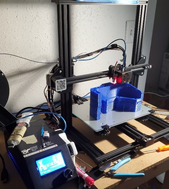
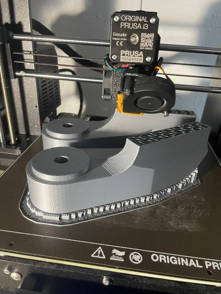
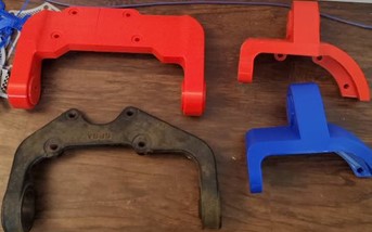
Figure 10: 3D printing the parts
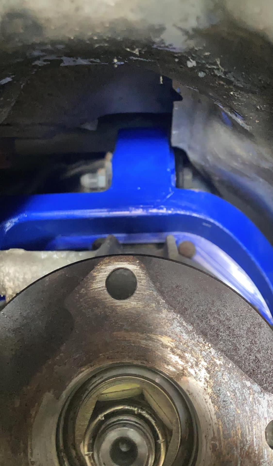
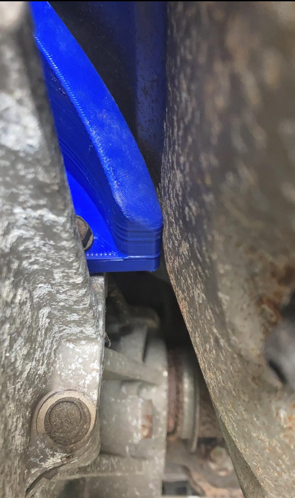
Figure 11: 3D printed parts were test fit on car and sometimes checked on CMM for accuracy
Levon Markossian - 2021


