HOME PAGE \
PDF SAMPLE DRAWINGS AVAILABLE
Isuzu Hub and Spindle
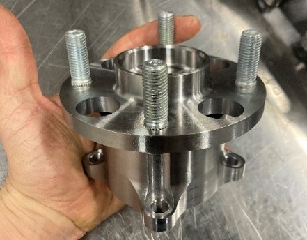
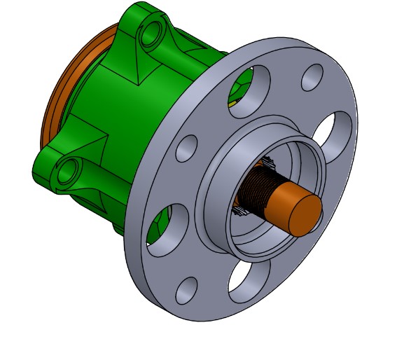
Figure 0: Finalized design.
Background
The Isuzu Impulse RS rear hub and spindle assemblies wouldn't last more than around 30,000 miles and since production was cut a long time ago, a high demand from enthusiasts was needed. The assembly is what the wheel bolts up to and spins on. As shown in figure 1, the factory design had ball bearings (also known as angular contact bearings) that ride in the hubs machined grooves. Once the assembly failed, the hub's interior was damaged, requiring a whole new assembly. This problem persisted ever since the car came out and it was never fixed. The re-designed assembly needed to last longer and cost no more than $ 500 per set (set contains two assemblies for each side of back wheels).
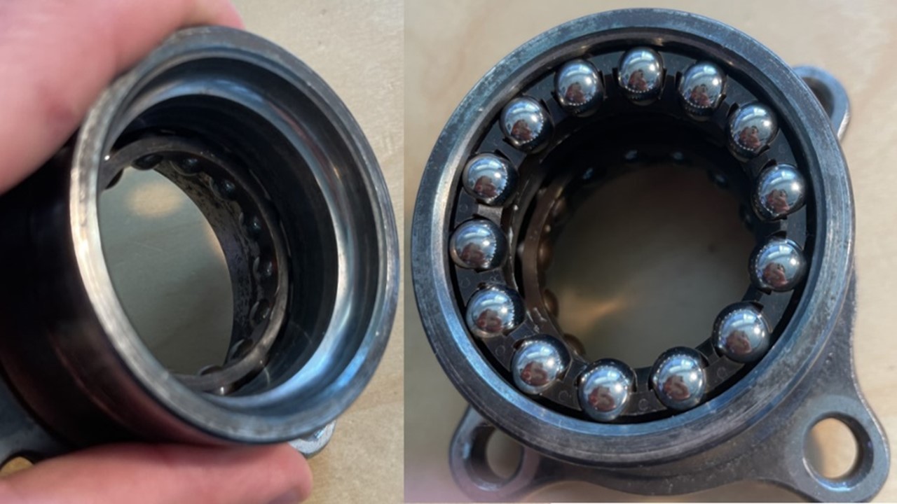
Figure 1: Factory hub's interior geometry machined (left) ball bearings installed (right).
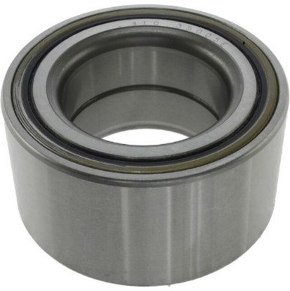
Figure 2: New selected roller beraing that can be pressed in hub.
Design Process and Constraints
- The new design utilized a dual row tapered roller bearing that was pressed into the hub (figure 2 & 3):
- Allows for replacement of bearing if failure occurs, instead of scrapping the entire assembly.
- Extended life and better control of the pre-load in the axial direction once assembly is torqued down.
- Cheaper manufacturing cost of the hub due to simplified interior geometry.
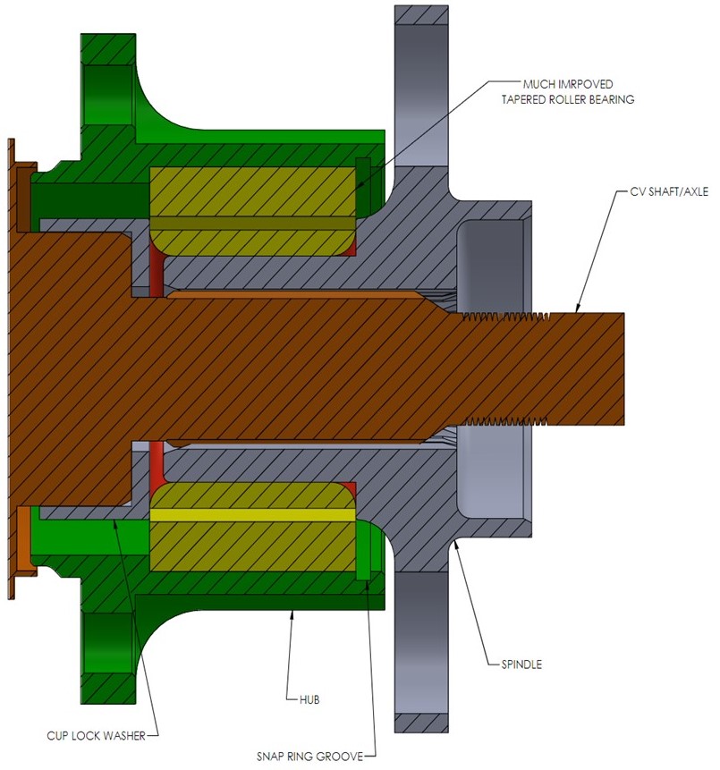
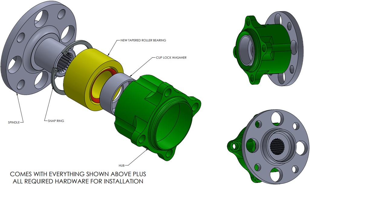
Figure 3: Nomenclature of assembly.
- Bearing needed to be compact and no more than 0.1 inch increase in diameter from factory hub's interior geometry:
- Size constraint due to bolting pattern of the hub itself and wheel speed sensor mounted nearby could not be moved (figure 4).
- Compact size of bearing was found at automotive parts store off a 2007 Toyota Corolla; readily available for enthusiasts to buy if needs replacing.
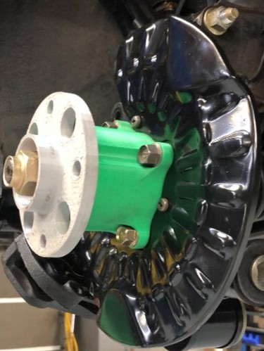
Figure 4: 3D print test fit.
- Spline reverse engineering challenging due to lack of CNC gear checker, but workarounds possible:
- Female spline data was taken off an optical comparator and vision system (figure 5).
- Male spline data taken from measurement over pins.
- Female and male spline data compared by calculating their involute curves on SolidWorks equation tool.
- Spline was cut into a 0.5 inch steel plate in wire EDM cutter to test fit of male spline ensuring proper backlash and smooth engagement (figure 5). This also confirmed spline standard and applicable specifications if broached.
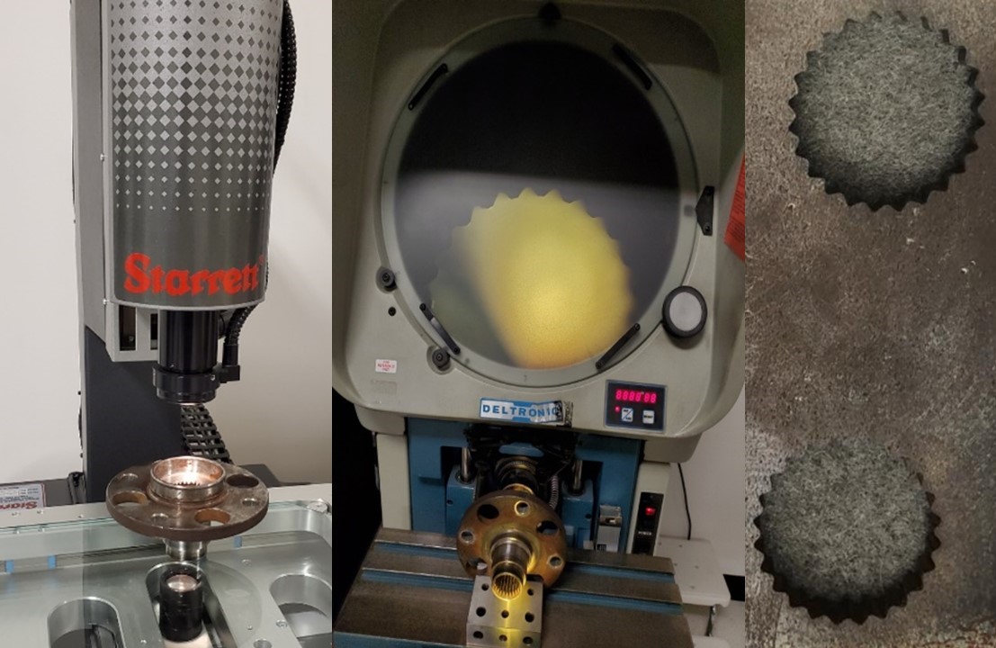
Figure 5: Vision system (left), optical comparator (middle), Wire EDM Cut (right).
Manufacturing and Results
- Manufacturing was done in China and final assembly of bearings and wheels studs was done in house by business partner:
- Multiple quotes were sent out and all yielded similar profits of around 140%.
- Samples were checked on a manual CMM. GD&T issues worked out via email and videos explaining issues.
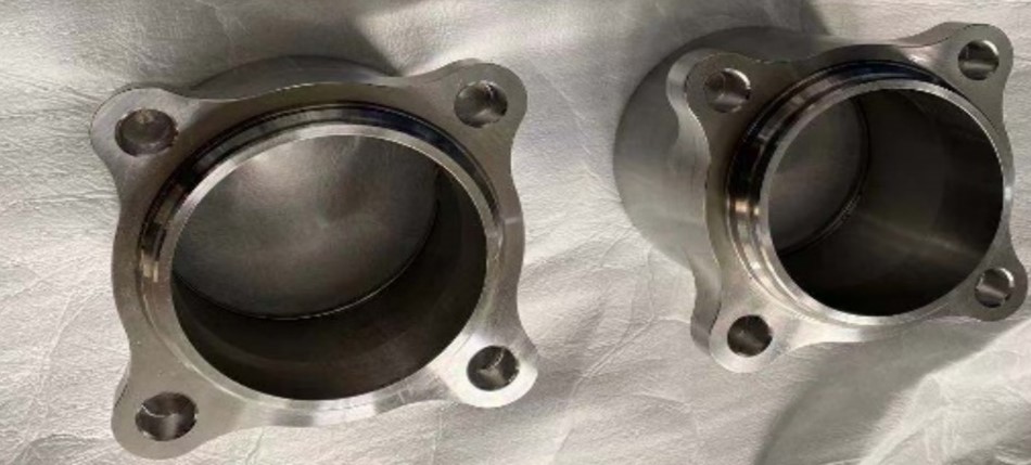
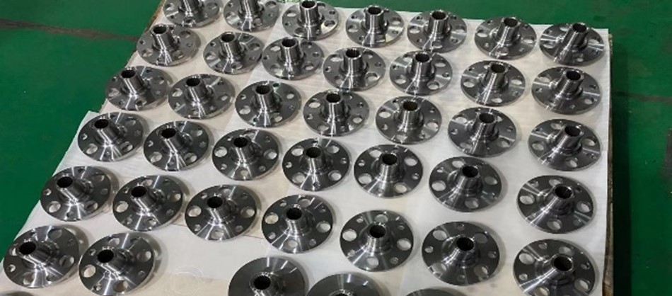
Figure 6: Machining done overseas.
- 87 sets were made and shipped all over the world. No issues or complaints reported.

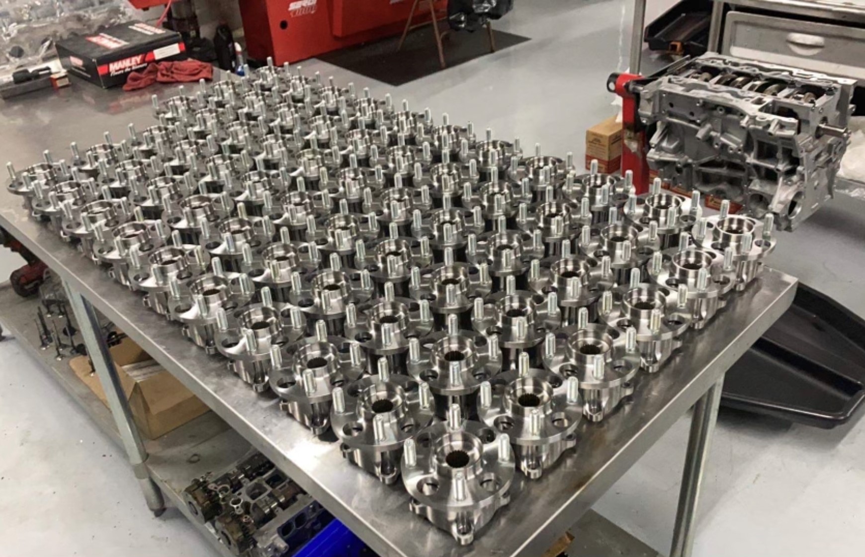
Figure 7: Final assembly of pressing bearing, sprindle, and wheel studs done in house by business partner.
Levon Markossian - 2021


